
Tutorial of update controller SN number
Software Architecture
| file/folder | Comment |
|---|---|
| lib | Python lib |
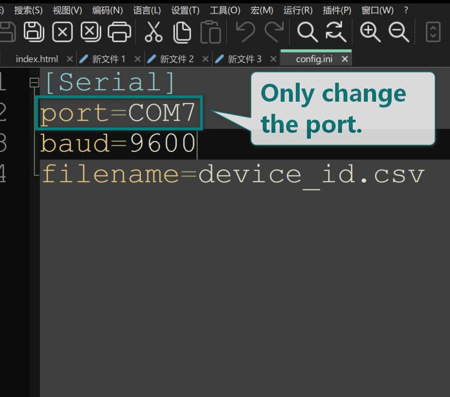
| config.ini | config the serial port |
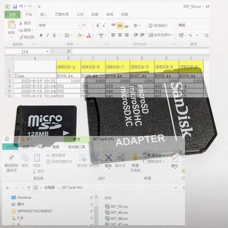
| device_id.csv | Serial number file |
| z0a.exe | main exe file |
Steps
Step 1, update the COM port to config.ini
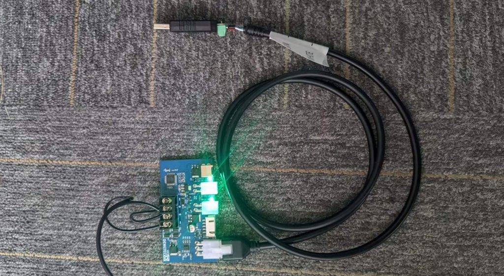
- insert the RS485 -> USB devcie to USB port.
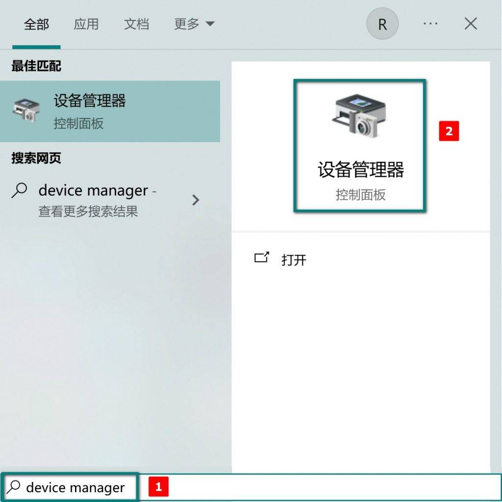
- open (device manager)
- find the COM name.
- The name of the com port may not be the same as in the screenshot, please use the name on your computer.
- update the config.ini file

Step 2, prepare the new serial number
- open device_id.csv by excel or others text editor.
- input the serial number(Decimal numbers) in SN colum, max:65535(0xFFFF)
Please refer to the device_id.csv file in the compressed package
Step 3, update the serial number
- Open a cmd window in the current directory and enter
- run z0a
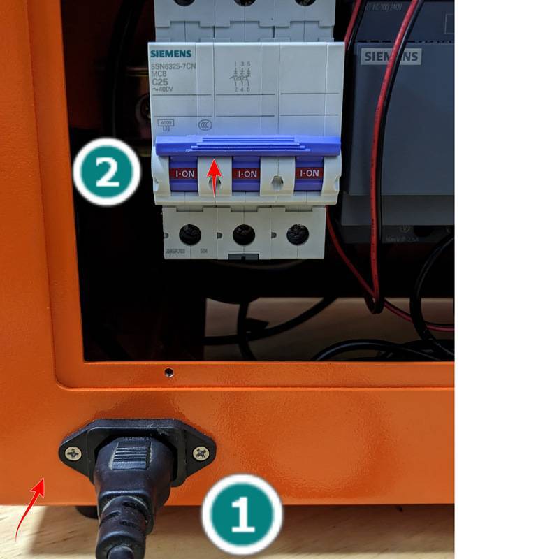
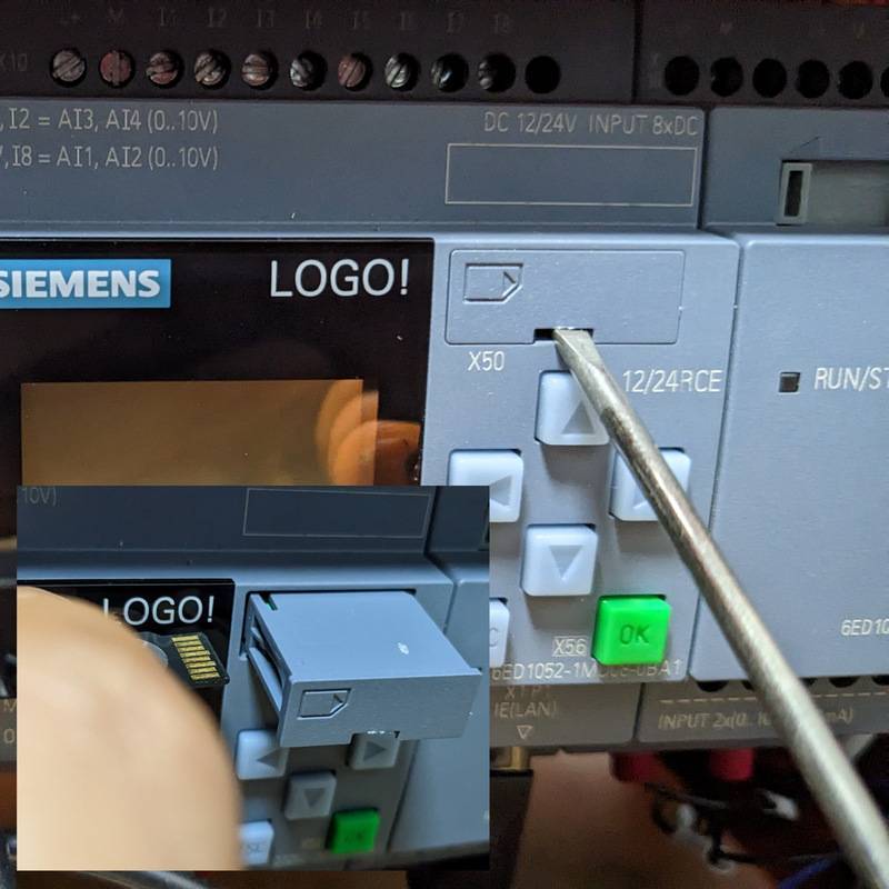
- connect the contoller to RS485
- choose the Serial Number you already prepared in device_id.csv file
- disconnect the current controller and start the process of connecting to the next controller